555 Timer Schematic Symbol / Results Page 126 About Up Down Counter With Cd40110be Searching Circuits At Next Gr - There are a lot of projects out there using the 555.
555 Timer Schematic Symbol / Results Page 126 About Up Down Counter With Cd40110be Searching Circuits At Next Gr - There are a lot of projects out there using the 555.. The circuit symbol for a 555 (and 556) is a box with the pins arranged to suit the circuit diagram: The power of a resistor can be derived from general electric power formula: Under the library manager\component tab, select wizard and create a component by assigning the schematic symbol and pcb symbol in the dialog with the pin assignment and click the finish button. The pin diagram of a 555 timer ic is shown in the following figure −. Usually just the pin numbers are used and they are not labelled with their function.
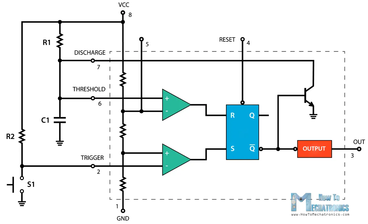
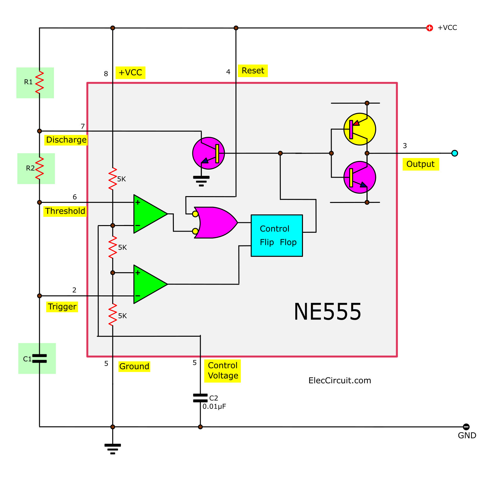
Awesome 555 timer ic projects · 1. If a 10uf timing capacitor is used, calculate the value of the resistor required to produce a minimum output time delay of 500ms. Its name is derived from three 5k ohm resistors ,connected in series used in it.the timer ic can produce 555 timer was first introduced by signetics corporation in 1971 as. Between the positive supply voltage v cc and the ground gnd is a voltage divider consisting of three identical resistors, which create two reference voltages at 1 ⁄ 3 v cc and 2. Pin configuration of the 555 timer here is the identification for each pin:
555 Timer Wiki Wiki Jmehan Com from wiki.jmehan.com If a 10uf timing capacitor is used, calculate the value of the resistor required to produce a minimum output time delay of 500ms. The following formulas can be used to calculate the frequency, period, duty cycle, high time and low time of the 555 timer in astable mode. Its name is derived from three 5k ohm resistors ,connected in series used in it.the timer ic can produce 555 timer was first introduced by signetics corporation in 1971 as. This ic consists of 23 transistors, 2 diodes and 16 resistors. These on off intervals can be adjusted by varying the 555 timer output and number of counter outputs. Most engineers understand what is inside a 555 timer ic. A monostable 555 timer is required to produce a time delay within a circuit. Octopart is the preferred search engine for electronic parts.
Derivatives provide two ( 556) or four ( 558) timing circuits in one package.
V = ir, i = v/r substituting either one in the p=iv gives. The ohm is the symbol of electrical resistance ω. The pin diagram of a 555 timer ic is shown in the following figure −. Operational amplifiers are voltage amplifiers with inputs and usually one output. Nov 05, 2011 · they have over 70,000+ readily available schematic in their web database along with 15,000+ pspice libraries. It was designed in 1970 by hans r. Camenzind for the signetics corporation. Here, with the help of the 555 timer ic, we are eliminating the need of manually switching on or off the device. Awesome 555 timer ic projects · 1. The pin configuration is shown in the figures. The second image is the schematic symbol of the 555 timer used in diagrams: Now the schematic symbol and pcb symbol are created for the 555 timer. Adjustable on off timer(using 555 astable mode) in this circuit a timer with cyclic on off operations is designed.
This circuit uses very basic components like 555 timer and 4017 counter. Between the positive supply voltage v cc and the ground gnd is a voltage divider consisting of three identical resistors, which create two reference voltages at 1 ⁄ 3 v cc and 2. 555 timer ic testing circuit and its working from www.electronicshub.org if you look closely, you will find the '.' symbol on digital pin 3,5,6,9,10, and 11. In this project, we are using 555 timer ic to create various timer circuit like 1 min timer circuit, 5 min timer circuit, 10 min timer circuit, and 15 min timer circuit. The 556 is less popular and may cost more than two 555s so you may prefer to use two 555 timers.
555 Timer Ic Working Principle Block Diagram Circuit Schematics from howtomechatronics.com A model consists of a subcircuit and a symbol. There is no 555 timer though, so let's create our own. 555 timer was first introduced by signetics corporation in 1971 as se555/ne555. Operational amplifiers are voltage amplifiers with inputs and usually one output. The 555 timer is a simple integrated circuit that can be used to make many different electronic circuits. Camenzind for the signetics corporation. F is the symbol for frequency and is measured in hertz (hz). In this video we look at a simple 555 astable circuit.
555 timer ic schematic diagram / astable multivibrator using 555 timer circuit diagram / if you would like to use any of these ideas, do some testing before using the lm555 or lm556 timer in an actual circuit.
This ic consists of 23 transistors, 2 diodes and 16 resistors. Here, with the help of the 555 timer ic, we are eliminating the need of manually switching on or off the device. This will help you instantly recognise the function of each pin: The 555 timer is probably the most common and popular ic to be used in hobby circuits. When drawing a circuit diagram, always draw the 555 as a building block, as shown below with the pins in the following locations. F is the symbol for frequency and is measured in hertz (hz). It monitors the charging of the timing capacitor in astable and monostable circuits. Camenzind for the signetics corporation. The 555 timer ic is an integrated chip used in a variety of timer, pulse generation, and oscillator applications. The following formulas can be used to calculate the frequency, period, duty cycle, high time and low time of the 555 timer in astable mode. To make the 555 timer circuit you will also need several other components. 500ms is the same as saying 0.5s so by rearranging the formula above, we get the calculated value for the resistor, r as: Nov 05, 2011 · they have over 70,000+ readily available schematic in their web database along with 15,000+ pspice libraries.
This circuit shows an intruder alarm using 555. It was designed in 1970 by hans r. Press and hold down the left mouse button. C is the symbol for capacitance and is measured in farad (f). Most engineers understand what is inside a 555 timer ic.
How Does Ne555 Timer Circuit Works Datasheet Pinout Eleccircuit Com from www.eleccircuit.com This ic consists of 23 transistors, 2 diodes and 16 resistors. The circuit symbol for a 555 (and 556) is a box with the pins arranged to suit the circuit diagram: The 556 shares the power pins. Resistors are manufactured over a very large range of values from 1mω to 1kω to 1mω. I am using a 12v 2.7ah nimh battery and i am using 4 (4.5v) solar panels in series with a power rating of 1.5 w (each panel) and current rating of 0.334. Now both can be associated to define a component. In monostable mode, the duration for which the pin 3 would remain high, is given by the below formulae: It monitors the charging of the timing capacitor in astable and monostable circuits.
This circuit shows an intruder alarm using 555.
Awesome 555 timer ic projects · 1. 555 timer is an industrial standard ic existing from early days of ic. Finally, release the mouse button when the circuit symbol is in the required position. Resistors are manufactured over a very large range of values from 1mω to 1kω to 1mω. The 556 timer ic has 2 timing circuits dual timer, while the 558 timer ic has a total of 4 timing circuits. These on off intervals can be adjusted by varying the 555 timer output and number of counter outputs. The following formulas can be used to calculate the frequency, period, duty cycle, high time and low time of the 555 timer in astable mode. In this video we look at a simple 555 astable circuit. Also, 555 timer is used to generate an oscillating pulse. 555 timer was first introduced by signetics corporation in 1971 as se555/ne555. It monitors the charging of the timing capacitor in astable and monostable circuits. There are a lot of projects out there using the 555. 555 timer schematic symbol :
C is the symbol for capacitance and is measured in farad (f) 555 timer schematic. Being an integral part of electronics project, 555 timer ic is very often used in simple to complex electronics projects.


0 Komentar